The Socket Is the Interface

Socket biomechanics and variations of KD & TF prostheses: an interactive review.

SIPO 347 & 348 · Lecture Wed 30 Sep 2026
Photo: Cpl Richard Cave RLC (Phot), UK MOD, Wikimedia Commons, OGL v1.0
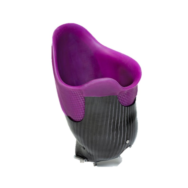
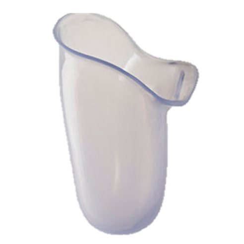
A clear transfemoral check socket
Start here

How to use this page

Each section matches the lecture. Look at the figures, then try the tool: flip the KD cards, run the plug-fit calculator, explore the QL walls, build an ICS lock, and pick a socket for a patient.

This review does not count towards your grade. The graded post-quiz is on Canvas.

Begin review
Section 2

KD socket variations

Section 3

Plug fit & quadrilateral

Section 3

Ischial containment

Section 3

MAS, NU-FlexSIV, HiFi

Section 2

KD socket variations

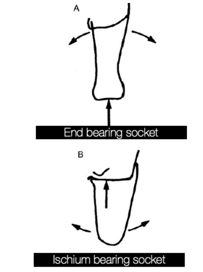
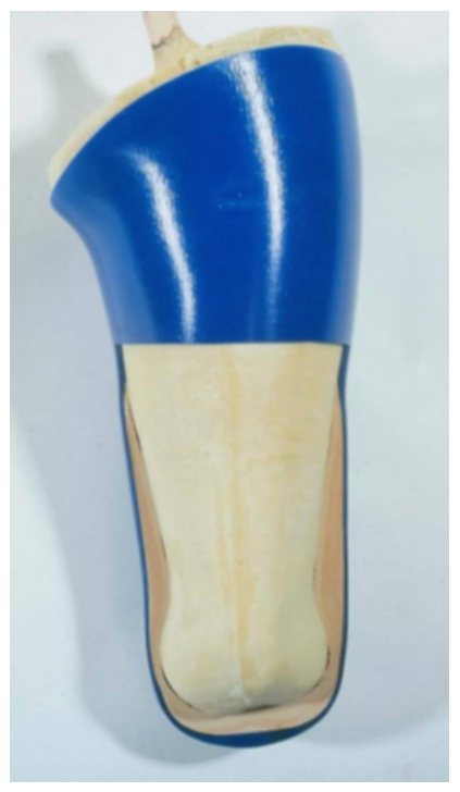
End-bearing lets a KD socket keep low trimlines. Tap each card to see when to use it and when to avoid it.

Figures: 2026 lecture, slides 23, 26, 28 and 30.

Diagram comparing an end-bearing KD socket with an ischium-bearing socket
If the end can take full load, the socket can stay low. If not, it needs a TF-style ischial brim. Figure: 2026 lecture, slide 21.

Try it: choose a KD socket

1. Can the distal end take full load?
2. Are the condyles well defined?
3. What matters most?
Section 3 · TF sockets

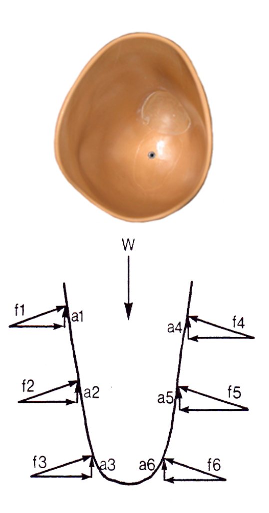
Why a plug fit squeezes the limb

Sloping walls push mostly sideways. Only the vertical part of each wall force holds the body up, so the total force on the limb can be far larger than body weight.

Try it: wall force calculator

Total wall force
× body weight

Model: ΣF = W × (1 − seat share) / sin(angle). Ignores friction. Class example: W = 600 N, 30°, no seat → 1200 N.

3.1 Quadrilateral socket

Explore the four QL walls

Choose a wall to see its job, its height and the key detail to check at fitting.

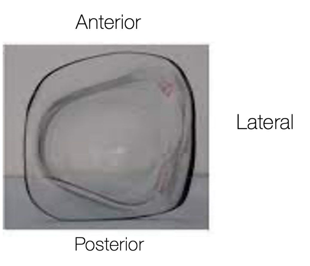
QL socket seen from above with anterior, posterior, medial and lateral labels
A QL socket from above: narrow A-P, wide M-L. Figure: 2026 lecture, slide 47.
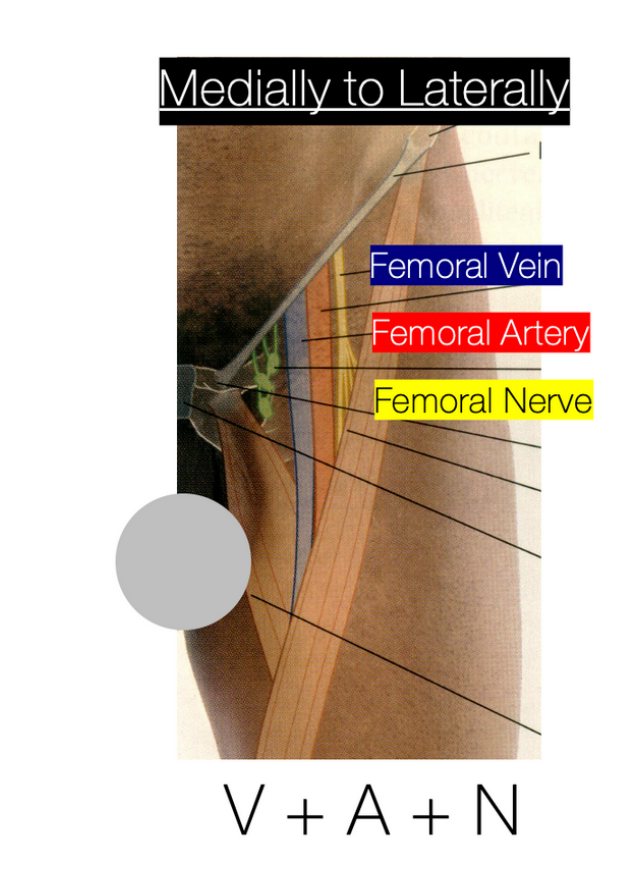
Front of the thigh showing the femoral vein, artery and nerve in Scarpa's triangle
Scarpa's triangle: femoral vein, artery and nerve from medial to lateral. The QL anterior wall pushes here, so pressure must be even. Figure: 2026 lecture, slide 54.
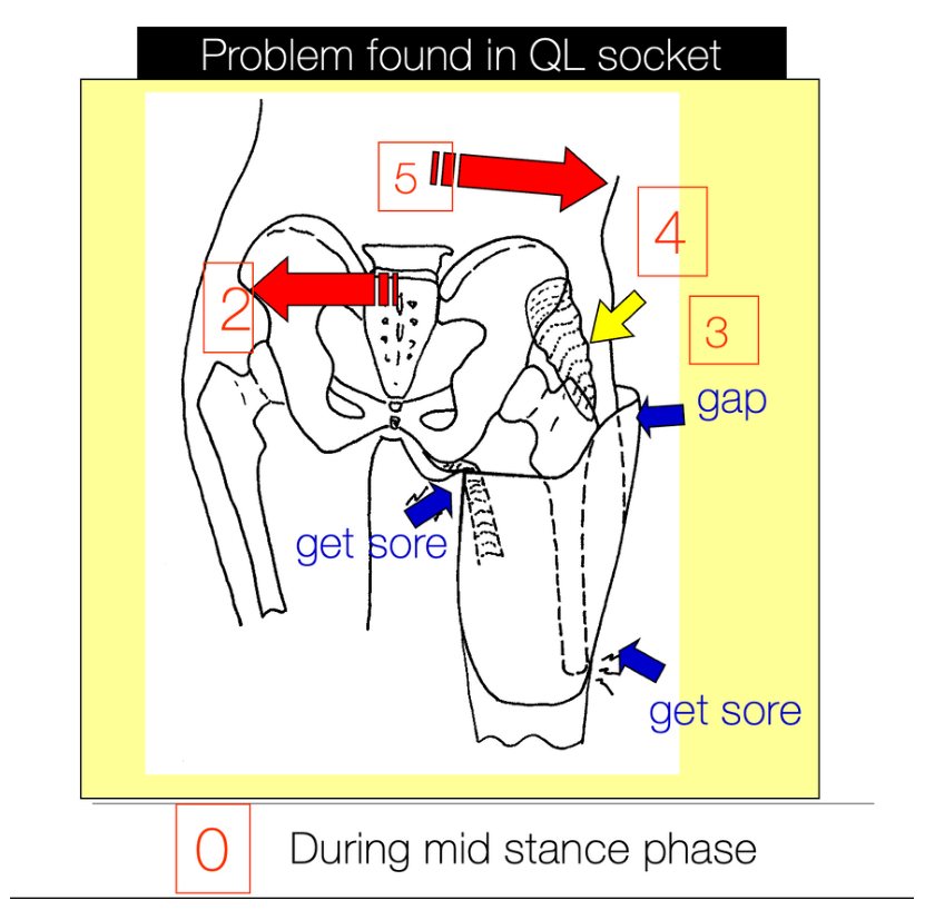
Diagram of the femur abducting inside a QL socket with gaps and pressure areas
The QL problem: the femur abducts in the wide socket → pelvis shifts medially → gap at the proximal lateral wall → abductors slacken → lateral trunk lean. Figure: 2026 lecture, slide 65.
3.2 Ischial containment socket

Build the ICS lock

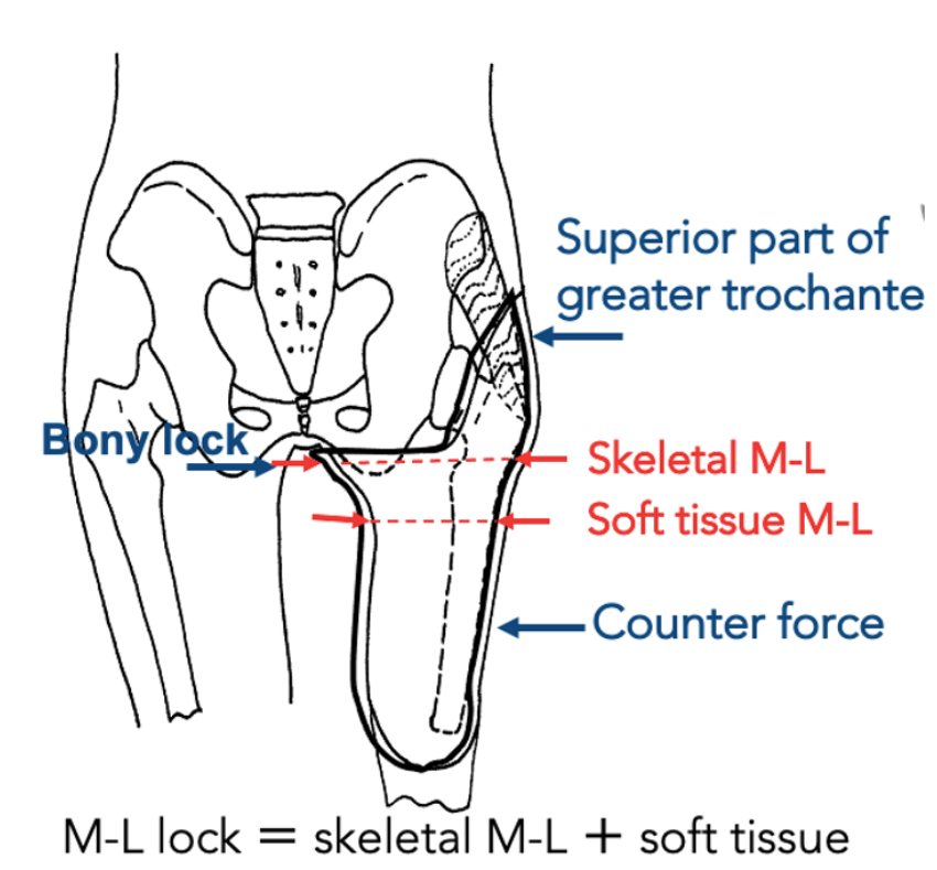
ICS is wide A-P and narrow M-L, and holds the ischium and ramus inside the socket. Lateral stability comes from three-point fixation.

Try it: three-point fixation

Teaching model: shows the direction of the effect, not real angles. M-L lock = skeletal M-L + soft tissue M-L.

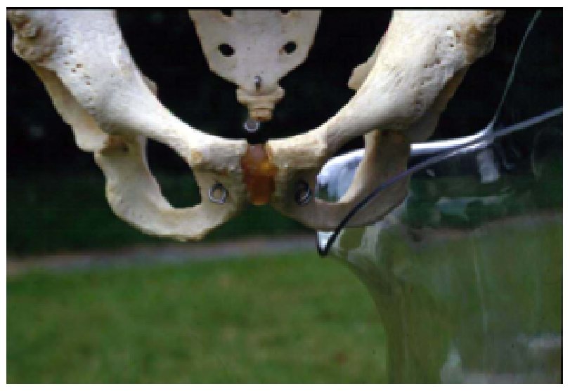
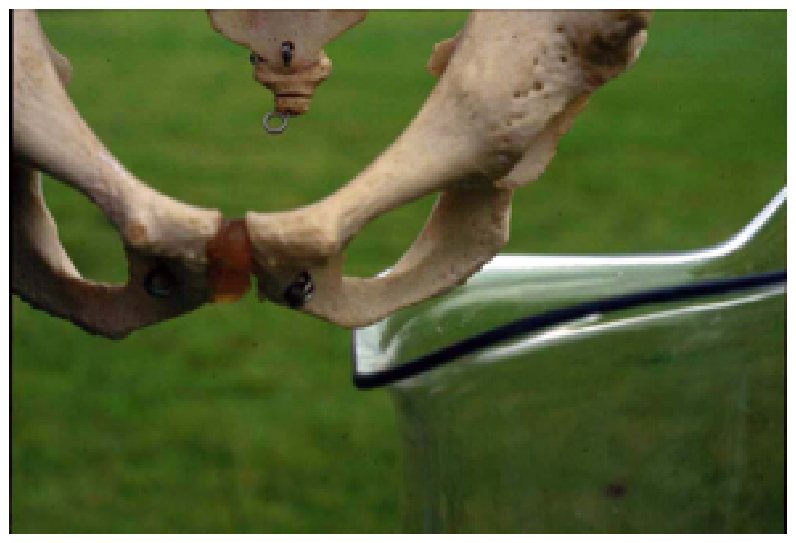
Ischial containment socket on a pelvis model, anterior view Quadrilateral socket on a pelvis model, anterior view QLICS

Slide to compare QL (left) and ICS (right) on the pelvis. Figure: 2026 lecture, slide 87.

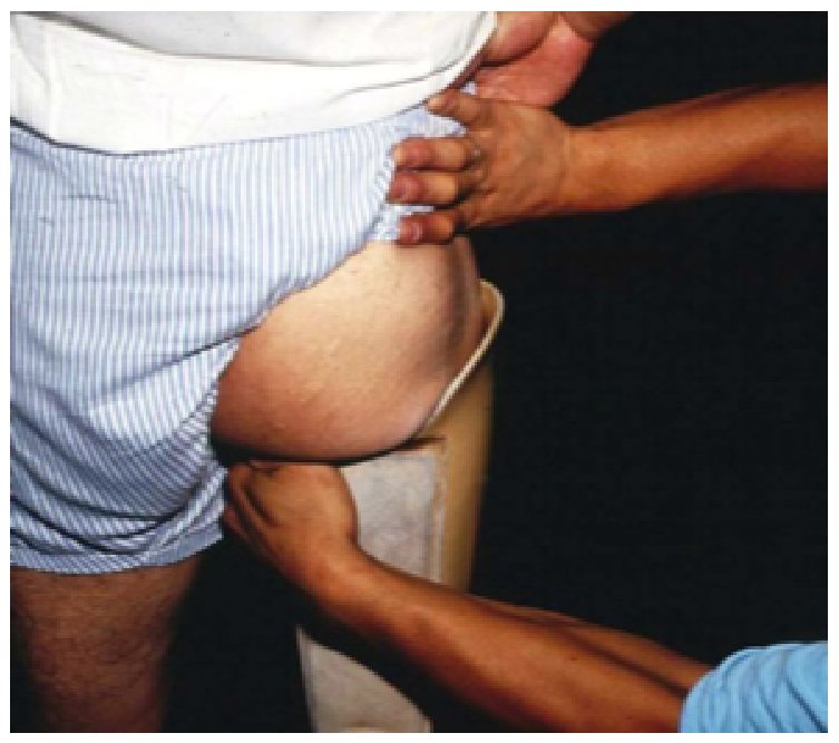
Hands testing a socket with no bony lock
No bony lock2026 lecture, slide 91.
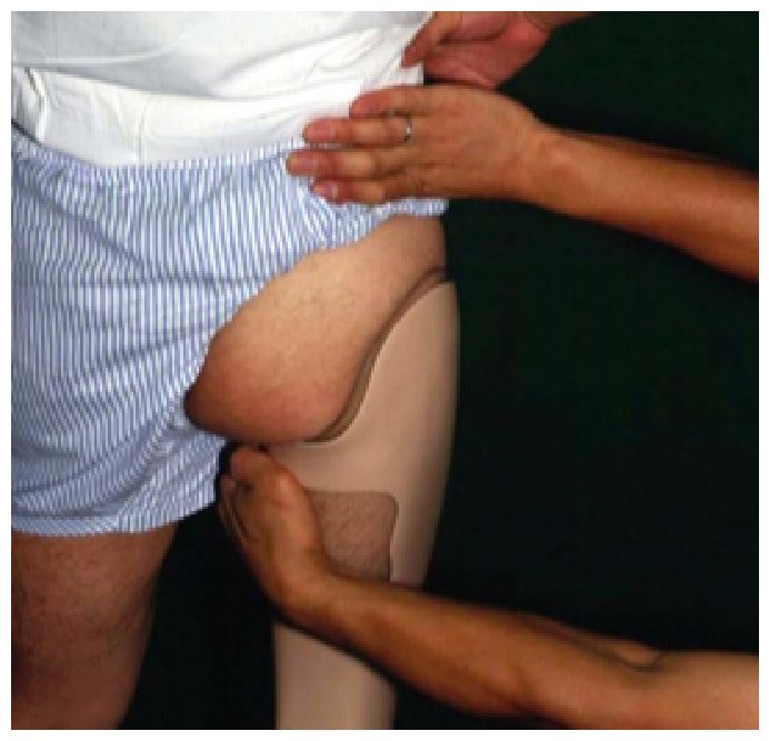
Hands testing a socket with a bony lock
Bony lock2026 lecture, slide 91.
3.3–3.5 Newer designs

Lower trimlines, more tissue control

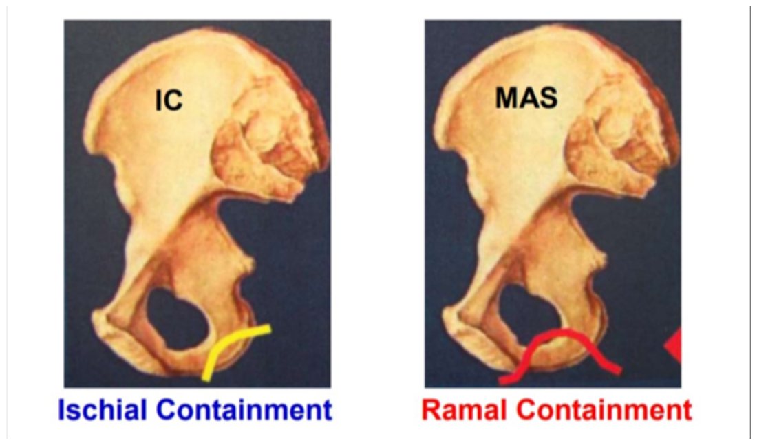
MAS, NU-FlexSIV and HiFi move away from pelvic encapsulation to free the hip.

Pelvis models comparing ischial containment with MAS ramal containment
3.3

Marlo Anatomical Socket

  • Ischial–ramal containment; medial wall parallel to the ramus
  • Low anterior and posterior trimlines; no gluteal encapsulation
  • Four force vectors; quasi-hydrostatic weight-bearing
  • Needs specific training and an accurate ramal fit

Figure: 2026 lecture, slide 107 (MAS technical seminar material).

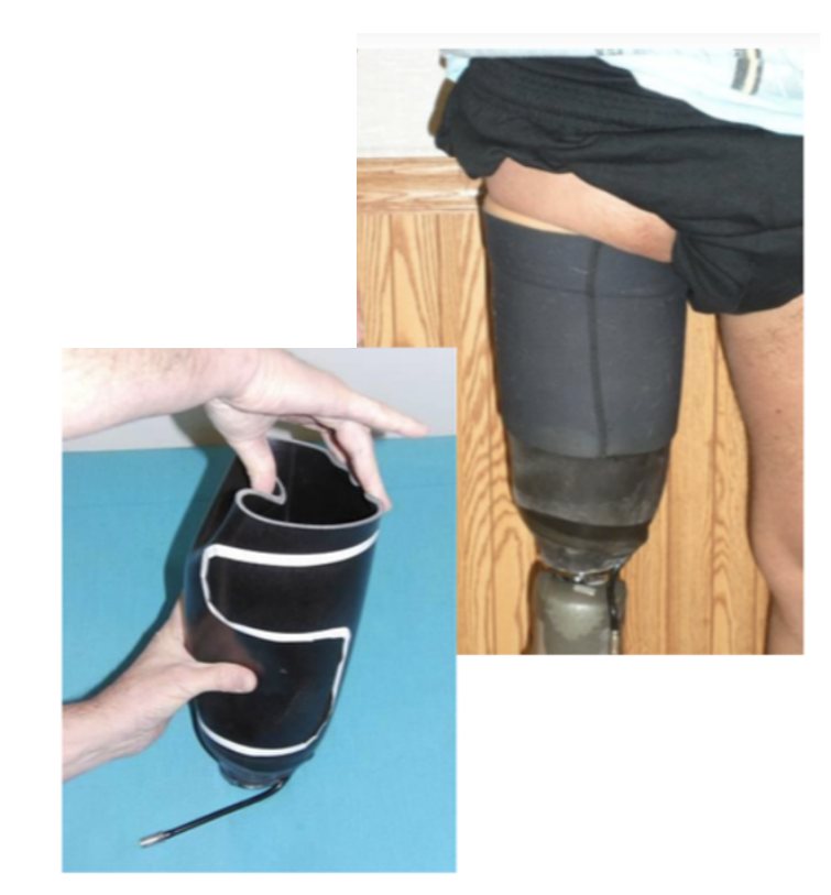
NU-FlexSIV subischial socket with flexible inner socket
3.4

NU-FlexSIV

  • Subischial: no contact with the pelvis
  • Stability from compressing the proximal soft tissue + vacuum suspension
  • For experienced users with a healed, stable, not-too-short limb
  • Early evidence: two-user case series (2017)

Figure: 2026 lecture, slide 115. Fatone S, Caldwell R. Prosthet Orthot Int. 2017;41(3):246-50.

Rectified transfemoral plaster models marked with compression and release areas
3.5

HiFi (compression–release)

  • Long bars compress tissue towards the bone along its length
  • Open windows let the displaced tissue go — without them it fails
  • Aims to cut “lost motion” between femur and socket
  • Concept paper, not a controlled trial

Figure: Alley RD, et al. J Rehabil Res Dev. 2011;48(6):679-96 (2026 lecture, slide 119).

Put it together

Socket selector

Describe a patient and see which TF designs fit best, and why. Try the three class cases.

Residual limb length
Limb volume
Skin
Prosthesis experience
Main goal

Teaching aid only. Real choices also depend on the patient's history, the team's skills and follow-up.

Self-check

Ten-question quiz

Each answer shows an explanation. This does not count towards your grade.

Score: 0 / 10
Go further

Recommended reading

Files are on Canvas.

Reading 1

Biomechanics of TF prostheses

Textbook chapter covering socket shapes and forces.

Atlas of Amputations and Limb Deficiencies (AAOS).

Reading 2

NU-FlexSIV Part 2: description and preliminary evaluation

How the subischial vacuum socket works and how two users did.

Fatone S, Caldwell R. Prosthet Orthot Int. 2017;41(3):246-50.

Reading 3

Compression–release stabilized sockets (HiFi)

The concept behind compression bars and release windows.

Alley RD, et al. J Rehabil Res Dev. 2011;48(6):679-96.

Classic

The ischial containment concept

Pritham's six objectives of the ICS.

Pritham CH. Prosthet Orthot Int. 1990;14(1):9-21.

Thai

ชีวกลศาสตร์ของเบ้าขาเทียม QL และ IC

Thai reading materials on QL and IC socket biomechanics.

Course materials (Canvas).